Laboratory of Ocean Ecosystem Dynamics
日本語
Tokyo University of Marine Science and Technology
Herminio Foloni Neto, Ph.D.
Ph.D., Tokyo University of Marine Science and Technology, Graduate School of Marine Science and Technology, 2015
M.S., University of São Paulo, 2010
B.S., Oceanographic Institute of the São Paulo, 2008
a. Design
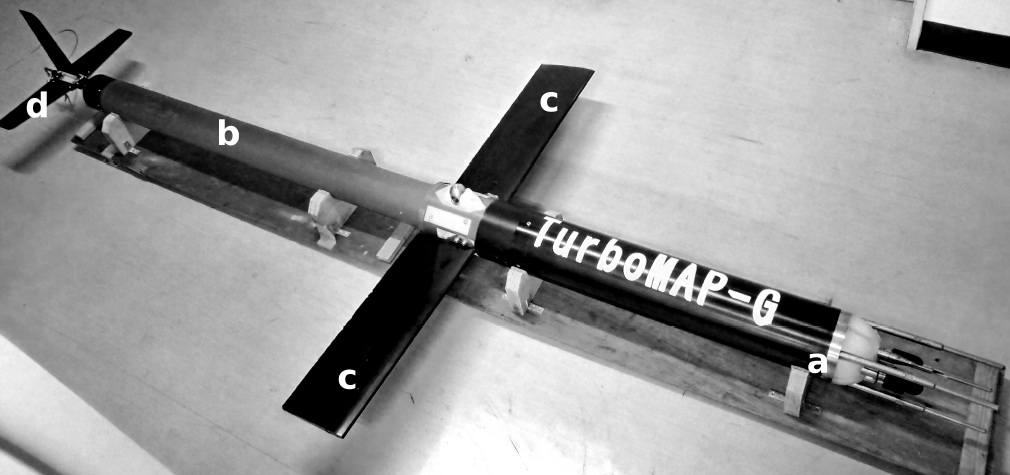
Fig. 1. The TMG basic configuration: a) acetal copolymer pressure case - head, where all the electronics and sensors are contained; b) aluminum pressure case - tail; c) main wings; d) tail wings.
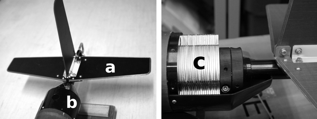
Fig. 2. a) tail wings; b) adjustable weight compartment; c) weight plates inside the compartment.
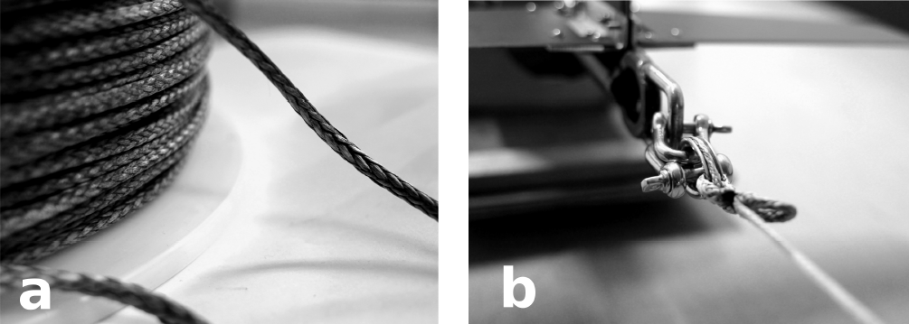
Fig. 3. a) HMWPEF - High Molecular Weight Polyethylene Fiber tethered cable used during deployment of the TMG; b) link between the tethered cable and the TMG (note that the cable does not provide any communication link).
The total length of TMG is 2.7 m, with a mass of 30.24 kg and a density of 1045.4 kg m-3; its configuration can be seen in Fig. 1. The TMG has two different pressure cases: the head is made of acetal copolymer containing all sensors; the tail pressure case, made of aluminum, coupled with the head and the tail wings at the opposite end section. The tail wings are positioned to stabilize the TMG flight and attached to them is an adjustable weight compartment that works as a horizontal stabilizer and helps to control pitch oscillations (Fig. 2).
The tethered cable, shown in Fig. 3a, is made of HMWPEF (High Molecular Weight Polyethylene Fiber) with a specific gravity in the water of 0.97 and a breaking strength of 900 kg. Its low weight (6 g m-1) and relatively low cost were the main advantages we considered when choosing this cable. Our cable does not provide real time data acquisition, since the main function is only during recovery (Fig. 3b). The TMG is an internally recording instrument and the communication (including glider's setup and data downloading) is made by a telemetry link interface that converts and transmits data from the TMG to a PC.
b. Sensors
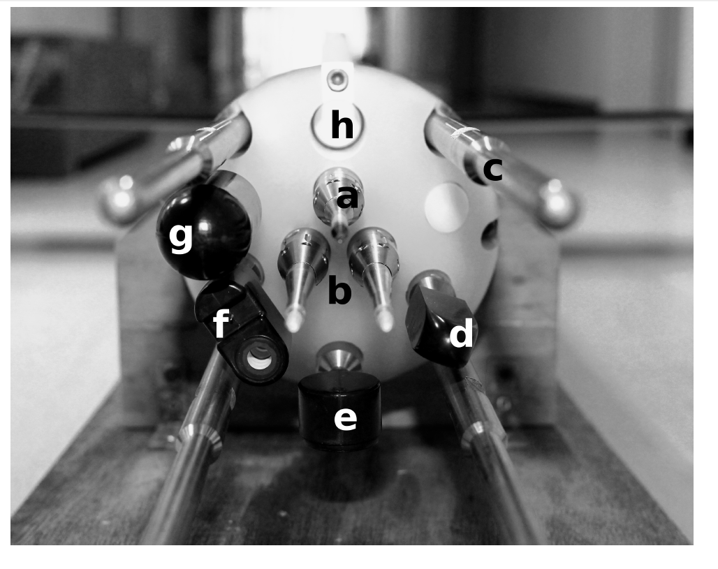
Fig. 4. a) FP07 thermistor; b) two velocity shear probes measuring in z-direction; c) guards that protect sensors from mechanical impact; d) laser fluorometer; e) LED fluorometer; f) conductivity and temperature sensors; g) electromagnetic flowmeter; h) pressure sensor.
The TMG carries two shear probes, both oriented to detect velocity fluctuations in z-direction with a sampling frequency of 512 Hz. The microstructure temperature is obtained from a FP07 fast thermistor probe with a sampling rate of 512 Hz. The light emitting diode (LED) fluorescence/turbidity probe and the laser fluorescence probe have a sampling rate of 256 Hz. The reduced sample volume of the laser probe (32 μl), in comparison with the LED probe (4 ml), allows for measurements of chlorophyll-a with increased spatial resolution (Doubell et al. 2009). The basic hydrographic parameters (conductivity, temperature and depth) are provided with a sample rate of 32 Hz. In addition, a 3-D axis accelerometer, an electromagnetic flowmeter and a compass (sampling rate of 512 Hz, 32 Hz and 32 Hz respectively) describe the TMG’s yawing, pitching and rolling movements, as well as its gliding/attack angle (see section d), velocity and direction. The location of the sensors and their details can be seen in Fig. 4 and Table 1, respectively.
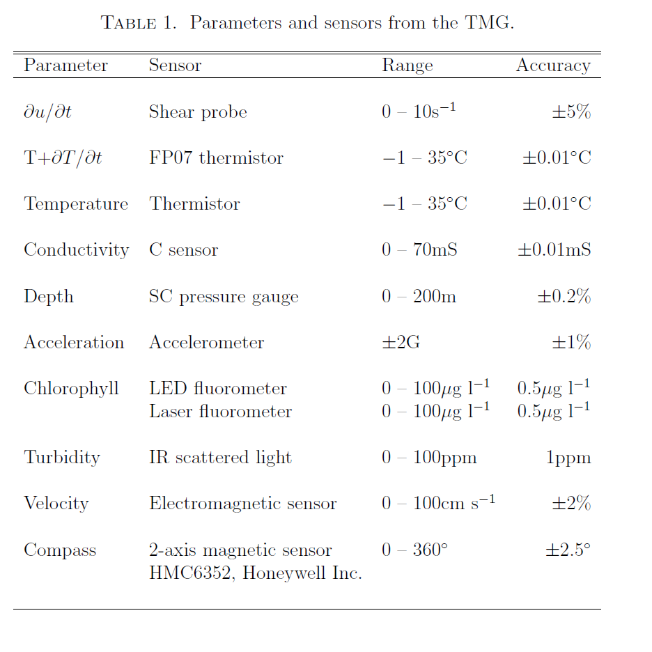
Table 1. Parameters and sensors from the TMG
c. Deployment
A launcher, designed for safe deployment from a supporting vessel, was used during the lowering of the TMG into the water surface. The launcher basically consists of a steel platform and two buoys located in the front in order to give a stabilizing effect on the platform. During the deployment, the TMG is attached to the launcher and lowered into the water surface by the ship's crane, as shown in Fig. 5a. Thereafter, the TMG is released (Fig. 5b), and the launcher is retrieved. The TMG descends immediately after its release. However, we pull it back to the water surface (Fig. 5c), and when the TMG nose starts to sink, the tethered cable is paid out manually. The cable needs always to be kept loose in order to avoid cable tension, and consequently interfering with TMG’s flight. Once observation ends, the TMG is pulled back to the surface manually or using a YODA Profiler winch (Masunaga and Yamazaki 2013) and placed on the launcher (Fig. 5d and e). Since there is no communication link between the TMG and the operator during deployment, we needed to estimate, based on the sinking velocity, when observation should be terminated.
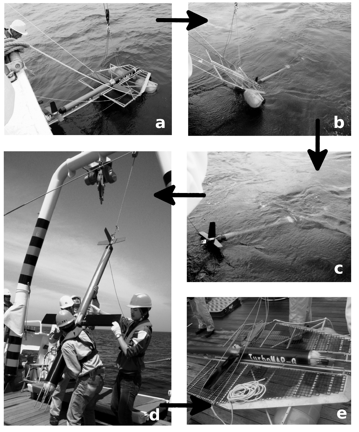
Fig. 5. Deployment of TMG from the R/V Seiyo-maru: a) the launcher coupled with the TMG is lowered to the water surface; b) the TMG is released, and the launcher is retrieved; c) the TMG is pulled back to the surface in order to start its free-fall; d) the observation is finished, and the TMG is brought onboard by using the ship's crane; e) the TMG is placed back on the launcher.
d. Performance
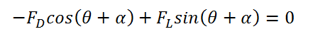
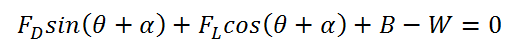
Following the model proposed by He et al. (2009) for predicting a glider’s performance, the force and moment equilibrium acting on the TMG in the horizontal (X) and vertical (Z) directions are:
 (1)
(1)
 (2)
(2)
 (3)
(3)
where θ is the pitch angle, α is the angle of attack of the TMG, (θ + α) is the path angle, and FD and FL are the drag and lift forces, respectively. B and W represent the buoyancy and the TMG weight, B - W is the net weight, and M represents the pitching moment. Coordinates (xB, zB) and (xm, zm) indicate the position of the center of buoyancy (CB) and the center of mass (CM) in the TMG coordinate system (see Fig. 6). We have taken zB = 0, since CB is on the major axis (x) of the glider.
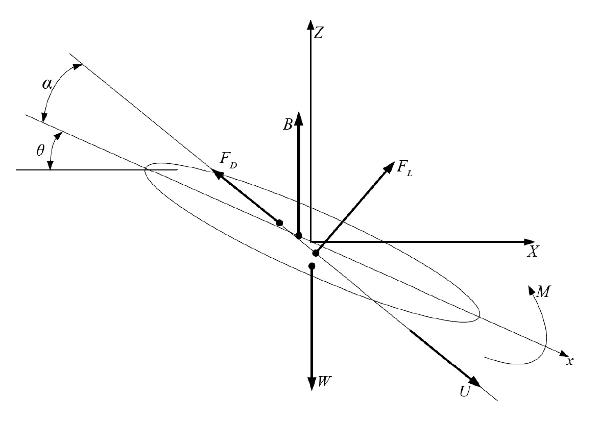
Fig. 6. The equilibrium of forces on TMG: U is the TMG speed, θ is the pitch angle, αis the angle of attack of the TMG, (θ + α) is the path angle, M represents the pitching moment, and FD and FL are the drag and lift forces, respectively. B and W represent the buoyancy and the force of gravity.